This goes over the screws and other pieces within the DSi XL along with differences in screws used on a per-color or per-console basis. There are Five Variations that I am aware of, and to my understanding, they are benign.
I originally posted this on Reddit, but I have learned a bit more since then. I will use a lot of information in that post as I believe my measurements are still accurate to my understanding. This is more of a formal post that is organized a bit better.
Eventually, I wish to do this with the DSi and, even further down the road, the 3DS line.
How I measured these screws.
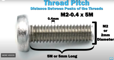
I measured the screws on a ruler with markings down to a single millimeter and a digital microscope. Measurements were taken similar to this image of measuring Thread Pitch below

Since I do not have specialty equipment to measure screws this small, I am forced to estimate. Take the measurements with the knowledge that it was done by someone who is a novice in screw measuring.
DSI XL
All Screws within the DSi XL have a JIS head, but a Phillips #00 works. Screws seem to be a variety of Wafer, Truss or Ultra Thin Head machine screws. Pan or Undersized Pan head is also possible. These are just my best guesses. I don't assign a head name to the screws as I don't know for certain.
Below is the list of screws and Hardware grouped by size. Further information is further down.
I'll add links to an IFixIt Guide to match my terms to pictures (i.e. Motherboard Black Screw would point to the Motherboard removal step of an IFitIt guide). The screw names themselves will have a link to the picture of the screw removal with another link next to it just encase that link dies.
Screws
2.5mm x 1.5mm x 2.5mm
Outer Shell Card Slot Screw (Step 4 Smallest Screw)
M1.4– 0.4mm x 2mm
2.5mm x 1.5mm x 2.5mm
Battery Daughter Board (Step 10), Small Motherboard Silver Screw (Step 17 Smallest Screw)
M1.4 – 0.6mm x 2mm
3.5mm x 1.5mm x 3mm
Black Shoulder Button Covers Right and Left (Step 8 for Right and Left), Motherboard Black Screws (Step 17 ), Top Screen Shell (Step 2), Top Screen Selfie Camera (Step 29)
M1.4 – 0.6mm x 3mm
4mm x 1.5mm x 3mm
Gold and Black SD/Stylus Cover (Step 10), and Gold Shoulder Button Covers.
M1.4– 0.6mm x 3.5mm
4mm x 1.5mm x 3.5mm
Battery Door Screw (Step 1)
M1.4 – 0.4 x 4mm
5mm x 1.5mm x 3mm
Bottom Shell (Step 4)
M1.4 - 0.6 x 4.5mm
Other
4mm width E-clip
5mm x 3mm x 1.5mm Battery Door Nut
6.5mm x 3.5mm Shoulder Button Spring
7mm x 1.25mm? Shoulder Button Pivot Post
Battery Door
I will sort the screw via disassembly order. For this, I will be borrowing IFixIt's images from their DSi XL Teardown to point to screws.

The battery door consists of Three Parts:
Two Screws:
M1.4 – 0.4 x 4mm
4mm x 1.5mm x 3.5mm
.jpg")

Two E-clips:
4mm Width
.jpg")
Two Rectangular Nuts.
These are lodged in the bottom shell.
5mm x 3mm x 1.5mm
.jpg")

Bottom Shell

This is where the first variation comes in.
All but Two Console Colors use Six Long Screws (Two Black and Four Silver) and One Short Black Screw. These are all of the console colors with the black bottom shell (Red, Yellow, Green, and Midnight Blue), and the Bronze and Burgundy consoles.

The US Exclusive Metalic Rose and JPN Exclusive Natural White use the same 6 Long screws, but only silver. It also uses a different silver small screw which is the same screw used on the Battery Daughter Board and the small screw on the MOBO (more on that later).

It is my understanding this is all for aesthetic reasons and the different small screw makes no structural difference. The decision to use the Silver Screws in place of the black screws makes sense as it would stand out less on the lighter-colored bottom shells.
For the Screws themselves:
Six Long Screws:
(Either Two Silver and Four Black or Six Silver)
M1.4 - 0.6 x 4.5mm
5mm x 1.5mm x 3mm

.jpg")
One Small Card Slot Screw:
Fine Thread.
M1.4– 0.4mm x 2mm
2.5mm x 1.5mm x 2.5mm
.jpg")

Motherboard and Power Daughter Board


The Motherboard and Powerboard are combined since the Motherboard Silver Screw in the top right corner is the same as the screws used on the power board. It saves space on this post.
Four Black Screws on the Motherboard:
M1.4 – 0.6mm x 3mm
3.5mm x 1.5mm x 3mm

.jpg")
Eight Small Silver Screws:
One Silver Screw on the Motherboard
Seven on the Power Daughter Board
This is the same screw mentioned for the Bottom Shell of the Pink and White DSi XL Consoles.
M1.4 – 0.6mm x 2mm
2.5mm x 1.5mm x 2.5mm
.jpg")

Upper Shell Screws


Five Silver Screws:
Four holding the upper shell and One within the shell holding the piece that covers the Selfie camera and microphone.
M1.4 – 0.6mm x 3mm
3.5mm x 1.5mm x 3mm

.jpg")
Bottom Shell (Shoulder Buttons and Stylus Cover)

This is where the other variation comes in.
To my knowledge, there are three variations in what screws were used.
One variation was all Seven Gold screws; similar to the IFixIt photo above.

Another used a mix of Four Black screws for the Shoulder Buttons and Three Golden Screws for the Stylus cover.

And the last used all Seven Black screws.

I was unable to find a pattern between which one had which set of screws, but I would guess that the later releases of the DSi XL had all Gold Screws as that makes the most economic sense.
Where it gets a little confusing is that not all black screws are the same, but all of the golden screws are. The black screws used for the Shoulder Buttons differ slightly from the ones used for the Stylus Cover.
Golden and Black Stylus Cover Screws:
These could be only 3 Golden Screws or the full Seven.
M1.4– 0.6mm x 3.5mm
4mm x 1.5mm x 3mm
.jpg")

Black Shoulder Button Screws:
At most Four.
M1.4 – 0.6mm x 3mm
3.5mm x 1.5mm x 3mm

.jpg")
Shoulder Button Hardware

These, being, the shoulder button pivots and the springs.
Two Shoulder Button Spring:
6.5mm x 3.5mm
.jpg")

Two Shoulder Button Pivots:
7mm x 1.25mm?
.jpg")

I originally posted this on Reddit, but I have learned a bit more since then. I will use a lot of information in that post as I believe my measurements are still accurate to my understanding. This is more of a formal post that is organized a bit better.
Eventually, I wish to do this with the DSi and, even further down the road, the 3DS line.
How I measured these screws.
I measured the screws on a ruler with markings down to a single millimeter and a digital microscope. Measurements were taken similar to this image of measuring Thread Pitch below
Since I do not have specialty equipment to measure screws this small, I am forced to estimate. Take the measurements with the knowledge that it was done by someone who is a novice in screw measuring.
DSI XL
All Screws within the DSi XL have a JIS head, but a Phillips #00 works. Screws seem to be a variety of Wafer, Truss or Ultra Thin Head machine screws. Pan or Undersized Pan head is also possible. These are just my best guesses. I don't assign a head name to the screws as I don't know for certain.
Below is the list of screws and Hardware grouped by size. Further information is further down.
I'll add links to an IFixIt Guide to match my terms to pictures (i.e. Motherboard Black Screw would point to the Motherboard removal step of an IFitIt guide). The screw names themselves will have a link to the picture of the screw removal with another link next to it just encase that link dies.
Screws
2.5mm x 1.5mm x 2.5mm
Outer Shell Card Slot Screw (Step 4 Smallest Screw)
M1.4– 0.4mm x 2mm
2.5mm x 1.5mm x 2.5mm
Battery Daughter Board (Step 10), Small Motherboard Silver Screw (Step 17 Smallest Screw)
M1.4 – 0.6mm x 2mm
3.5mm x 1.5mm x 3mm
Black Shoulder Button Covers Right and Left (Step 8 for Right and Left), Motherboard Black Screws (Step 17 ), Top Screen Shell (Step 2), Top Screen Selfie Camera (Step 29)
M1.4 – 0.6mm x 3mm
4mm x 1.5mm x 3mm
Gold and Black SD/Stylus Cover (Step 10), and Gold Shoulder Button Covers.
M1.4– 0.6mm x 3.5mm
4mm x 1.5mm x 3.5mm
Battery Door Screw (Step 1)
M1.4 – 0.4 x 4mm
5mm x 1.5mm x 3mm
Bottom Shell (Step 4)
M1.4 - 0.6 x 4.5mm
Other
4mm width E-clip
5mm x 3mm x 1.5mm Battery Door Nut
6.5mm x 3.5mm Shoulder Button Spring
7mm x 1.25mm? Shoulder Button Pivot Post
Battery Door
I will sort the screw via disassembly order. For this, I will be borrowing IFixIt's images from their DSi XL Teardown to point to screws.
The battery door consists of Three Parts:
Two Screws:
M1.4 – 0.4 x 4mm
4mm x 1.5mm x 3.5mm
Two E-clips:
4mm Width
Two Rectangular Nuts.
These are lodged in the bottom shell.
5mm x 3mm x 1.5mm
Bottom Shell
This is where the first variation comes in.
All but Two Console Colors use Six Long Screws (Two Black and Four Silver) and One Short Black Screw. These are all of the console colors with the black bottom shell (Red, Yellow, Green, and Midnight Blue), and the Bronze and Burgundy consoles.
The US Exclusive Metalic Rose and JPN Exclusive Natural White use the same 6 Long screws, but only silver. It also uses a different silver small screw which is the same screw used on the Battery Daughter Board and the small screw on the MOBO (more on that later).
It is my understanding this is all for aesthetic reasons and the different small screw makes no structural difference. The decision to use the Silver Screws in place of the black screws makes sense as it would stand out less on the lighter-colored bottom shells.
For the Screws themselves:
Six Long Screws:
(Either Two Silver and Four Black or Six Silver)
M1.4 - 0.6 x 4.5mm
5mm x 1.5mm x 3mm
One Small Card Slot Screw:
Fine Thread.
M1.4– 0.4mm x 2mm
2.5mm x 1.5mm x 2.5mm
Motherboard and Power Daughter Board
The Motherboard and Powerboard are combined since the Motherboard Silver Screw in the top right corner is the same as the screws used on the power board. It saves space on this post.
Four Black Screws on the Motherboard:
M1.4 – 0.6mm x 3mm
3.5mm x 1.5mm x 3mm
Eight Small Silver Screws:
One Silver Screw on the Motherboard
Seven on the Power Daughter Board
This is the same screw mentioned for the Bottom Shell of the Pink and White DSi XL Consoles.
M1.4 – 0.6mm x 2mm
2.5mm x 1.5mm x 2.5mm
Upper Shell Screws
Five Silver Screws:
Four holding the upper shell and One within the shell holding the piece that covers the Selfie camera and microphone.
M1.4 – 0.6mm x 3mm
3.5mm x 1.5mm x 3mm
Bottom Shell (Shoulder Buttons and Stylus Cover)
This is where the other variation comes in.
To my knowledge, there are three variations in what screws were used.
One variation was all Seven Gold screws; similar to the IFixIt photo above.
Another used a mix of Four Black screws for the Shoulder Buttons and Three Golden Screws for the Stylus cover.
And the last used all Seven Black screws.
I was unable to find a pattern between which one had which set of screws, but I would guess that the later releases of the DSi XL had all Gold Screws as that makes the most economic sense.
Where it gets a little confusing is that not all black screws are the same, but all of the golden screws are. The black screws used for the Shoulder Buttons differ slightly from the ones used for the Stylus Cover.
Golden and Black Stylus Cover Screws:
These could be only 3 Golden Screws or the full Seven.
M1.4– 0.6mm x 3.5mm
4mm x 1.5mm x 3mm
Black Shoulder Button Screws:
At most Four.
M1.4 – 0.6mm x 3mm
3.5mm x 1.5mm x 3mm
Shoulder Button Hardware
These, being, the shoulder button pivots and the springs.
Two Shoulder Button Spring:
6.5mm x 3.5mm
Two Shoulder Button Pivots:
7mm x 1.25mm?